
Each section of the exhaust line serves a specific function in the gas treatment chain, from the manifold to the rear silencer outlet. Correctly identifying a part on an exploded view diagram avoids ordering errors and unnecessary returns, especially when references vary between petrol and diesel engines of the same model.
Reading an exploded view diagram: assembly markers and referencing pitfalls
An exploded view diagram breaks down the exhaust line into numbered segments, each associated with a manufacturer (OEM) or supplier reference. The difficulty lies not in the visual recognition of the parts, but in interpreting the connection dimensions: outer diameter of the pipe, spacing of the studs on the flange, type of gasket (flat, conical, braided).
We regularly observe confusion between two intermediate silencers that have the same shape but differ in inlet diameter by a few millimeters. On a Peugeot 308 1.6 BlueHDi, for example, the intermediate pipe has a different length depending on whether the vehicle is equipped with an additive DPF or a catalyzed DPF. The exploded diagram remains the only document that can clarify this ambiguity before ordering.
To effectively utilize the exhaust line diagram, we recommend always starting from the manifold (fixed point, bolted to the cylinder head) and moving towards the rear of the vehicle while checking each connection. This sequential reading eliminates section inversions, which are common on dual silencer lines.
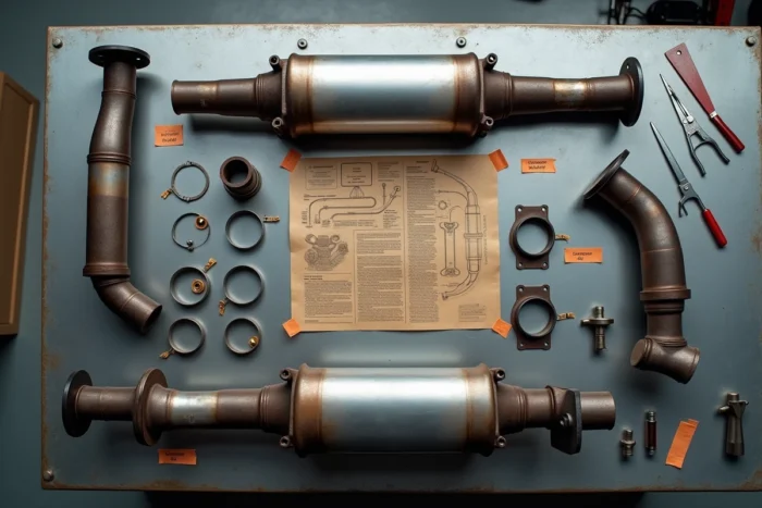
Manifold and catalyst: two parts often confused on the diagram
On recent engines, the manifold and the catalyst form a monolithic block. Parts catalogs then list a single assembly, sometimes called “catalytic manifold,” with a unique reference. Searching separately for a manifold and a catalyst on these vehicles leads to a dead end.
In contrast, on older architectures or certain atmospheric petrol engines, the catalyst is bolted downstream of the manifold via a flange with two or three studs. The exploded diagram then clearly distinguishes the two elements and shows the flange gasket between them.
- 4-in-1 manifold: four pipes converge into a single outlet, typical of inline four-cylinder engines. The crack almost always occurs at the weld between a pipe and the central body.
- 4-in-2-in-1 manifold: two pairs of pipes merge before joining a common pipe. This geometry improves gas scavenging at certain RPMs but complicates partial replacement.
- Integrated manifold-catalyst assembly: no intermediate flange. Replacement requires changing the entire block, significantly altering the budget.
DPF, silencers, and sensors: identifying each element downstream of the catalyst
Downstream of the catalyst, the line becomes more complex on diesel engines with the presence of the particulate filter (DPF). On the diagram, the DPF is identified by its oval or wide cylindrical shape, significantly bulkier than a simple silencer. It is positioned between the catalyst and the first silencer, sometimes integrated into the catalyst itself (referred to as a catalyst-DPF).
The Euro 7 standard, validated by the European Parliament in March 2024 and scheduled for July 1, 2030, will strengthen durability requirements for these devices. Future exhaust lines will incorporate more sensors (differential pressure, temperature, NOx) directly welded or screwed onto the DPF and the catalyst. The number of sensors on a line will increase from two or three to five or six depending on the architectures.
The lambda sensors, upstream and downstream of the catalyst, appear on the diagram as small threaded connectors. Their exact position is crucial: an upstream lambda sensor (known as “regulation”) does not have the same cable length or connector as a downstream sensor (known as “diagnostic”). Ordering “a lambda sensor” without specifying its position on the diagram almost guarantees an incompatible part.

Front silencer and rear silencer
The front silencer (or expansion chamber) reduces the pressure of the gases exiting the catalyst or DPF. The rear silencer provides final noise attenuation. On the exploded diagram, they are distinguished by their volume and the diameter of their inlet and outlet pipes.
The rear silencer is the part most often replaced because it is directly subjected to condensation and salt splashes in winter. Its corrosion does not mean that the rest of the line is faulty. Checking the diagram before intervention prevents replacing a healthy section out of excessive caution.
Gaskets, clamps, and supports: the invisible parts that can ruin an installation
Exploded view diagrams systematically represent flange gaskets, tightening clamps, and rubber suspension bushings. These parts are often the most neglected during an order. A crushed flange gasket cannot be reused: its sealing surface is deformed after the first tightening.
- Flat graphite gasket: used between the manifold and catalyst on many petrol engines. Deteriorates if tightened beyond the prescribed torque.
- Conical gasket (olive): common at the catalyst outlet. Does not require a flange, but a specific clamp with a precise tightening angle.
- Rubber bushings: fixed to the body, they keep the line suspended. Their breakage causes vibrations and knocking noises often wrongly attributed to the silencer itself.
- Band clamps: their diameter varies according to the section. A clamp that is too wide will not compress the gasket, while a clamp that is too tight will deform the pipe.
Each clamp and gasket appears on the exploded diagram with its own reference. Ignoring them when ordering necessitates a second trip to the workshop, doubling labor costs.
The exhaust line remains a mechanical assembly where each section depends on the previous one. Starting from the exploded diagram to compile a complete list of parts, gaskets, and fasteners before any order remains the most reliable method to avoid back-and-forth with the supplier.